Most people associate NACA profiles with aircraft wings, which makes sense considering where the system came from, but they have a lot to do with boats as well. The same NACA 0012 or 0015 sections keep appearing in rudders, keels, stabilizer fins, CFD studies and marine research, so understanding what those numbers actually mean is pretty useful.
A NACA profile is not really an aircraft part by itself, it is simply a defined two-dimensional section; put that section in air and it becomes an airfoil, put it in water and we are dealing with a hydrofoil section. The operating conditions obviously change, but the geometry gives us a controlled starting point for understanding what the flow is doing around it.
The NACA system was developed by the National Advisory Committee for Aeronautics, the organization that later became part of NASA. During the 1930s, NACA developed systematic families of airfoil sections and introduced a numerical naming system that allowed an engineer to understand important parts of the geometry directly from the name. Almost a century later, profiles such as NACA 0012 are still used constantly in research because the geometry is simple, well documented and supported by a huge amount of experimental data.
What a profile actually describes
Before getting into the numbers, it helps to separate the two-dimensional profile from the complete rudder, keel or foil: the profile is only the cross-section, so if I cut through a rudder horizontally and look at that cut, the outline I see is the profile.
The easiest dimension to start with is the chord, the straight distance from the leading edge to the trailing edge; thickness is then measured relative to that chord, while camber describes how far the mean line curves away from it. If there is no camber, the section is symmetric and the upper and lower shapes are the same.
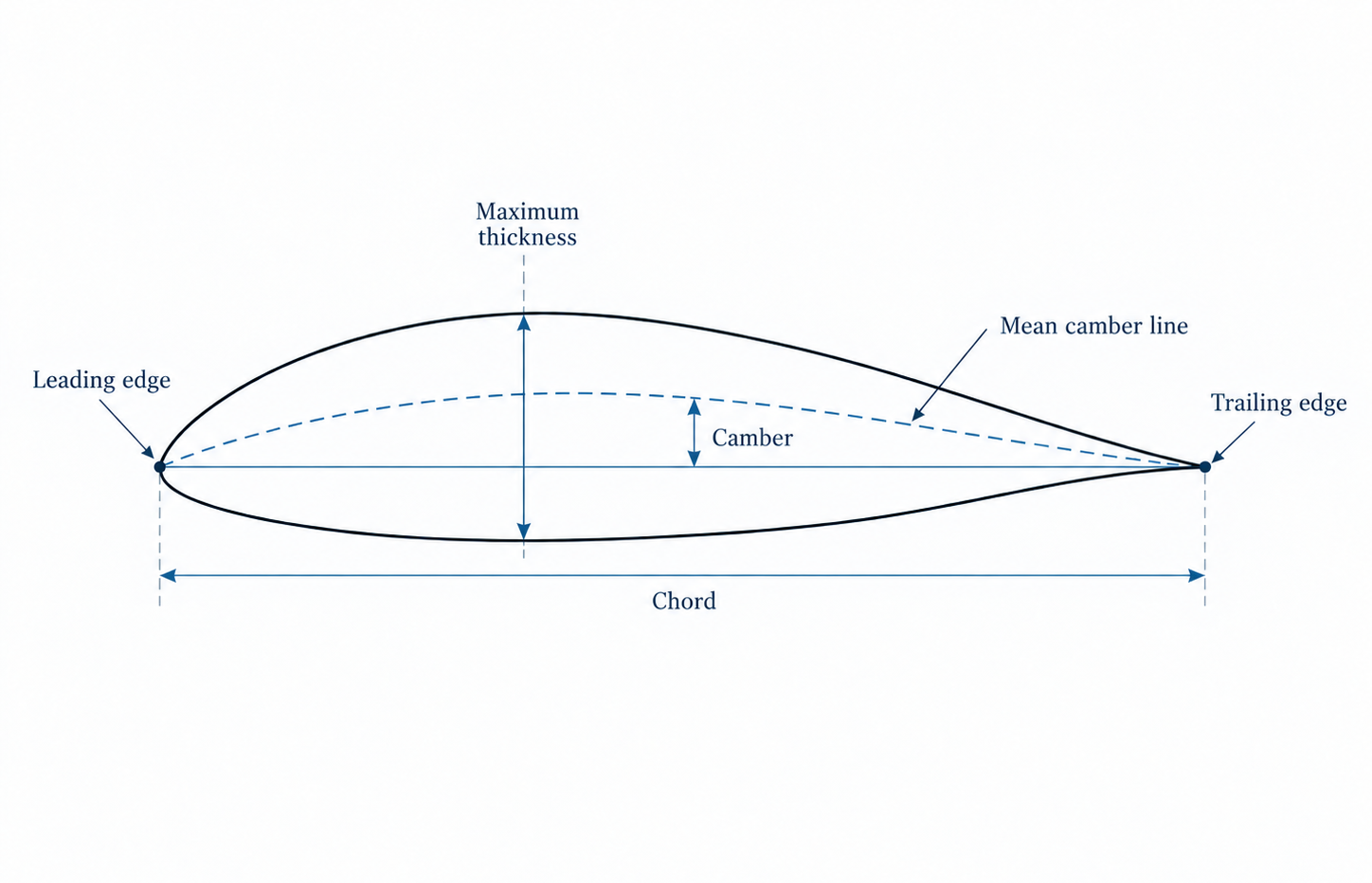
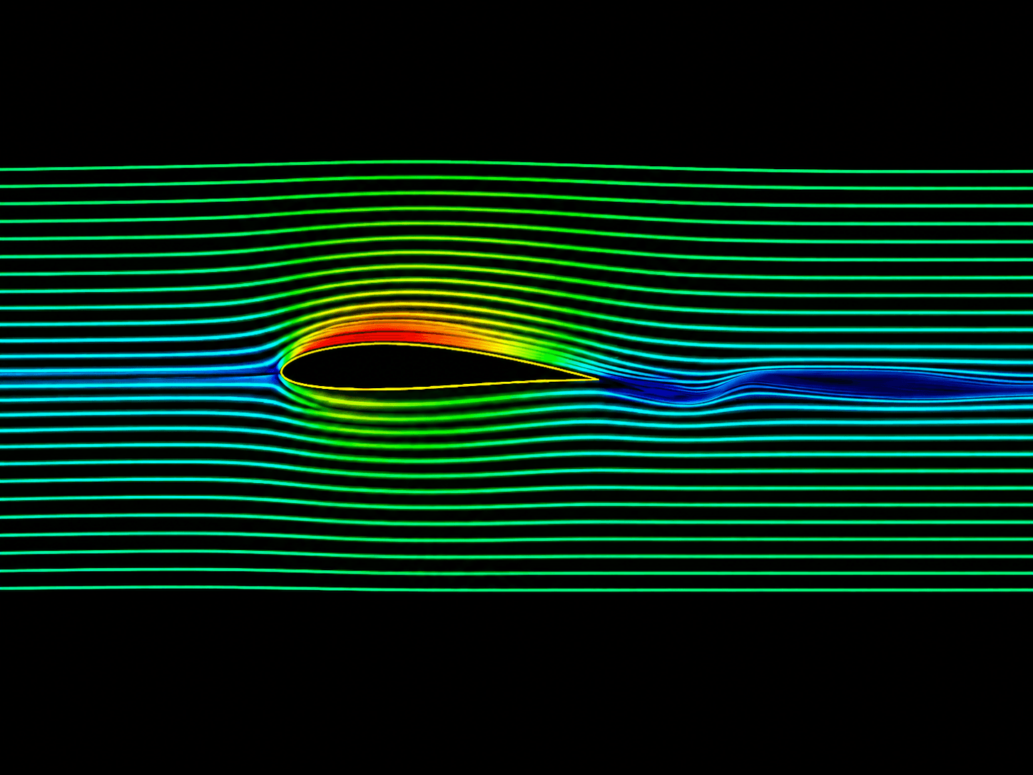
Changing that shape changes the pressure around the surface, and the rest follows from there. The force the foil produces starts to move with it, then at higher angles the question becomes how long the flow can stay attached; in water, if the local pressure drops far enough, cavitation can start.
Reading NACA 0012
The four-digit NACA system is probably the easiest place to start because the name itself already contains useful geometry.
Take NACA 2412:
| Digit | Meaning | NACA 2412 |
|---|---|---|
| First digit | Maximum camber as % of chord | 2% |
| Second digit | Position of maximum camber in tenths of chord | 40% chord |
| Last two digits | Maximum thickness as % of chord | 12% |
So NACA 2412 has 2% maximum camber located at 40% of the chord, with a maximum thickness of 12% of the chord.
NACA 0012 becomes much easier to read after that: the first two digits are zero, so there is no camber, while the last two tell us the maximum thickness is 12% of the chord. NACA 0015 follows exactly the same logic but increases that thickness to 15%.
| Profile | Camber | Camber position | Maximum thickness |
|---|---|---|---|
| NACA 0012 | 0% | Symmetric | 12% chord |
| NACA 0015 | 0% | Symmetric | 15% chord |
| NACA 2412 | 2% | 40% chord | 12% chord |
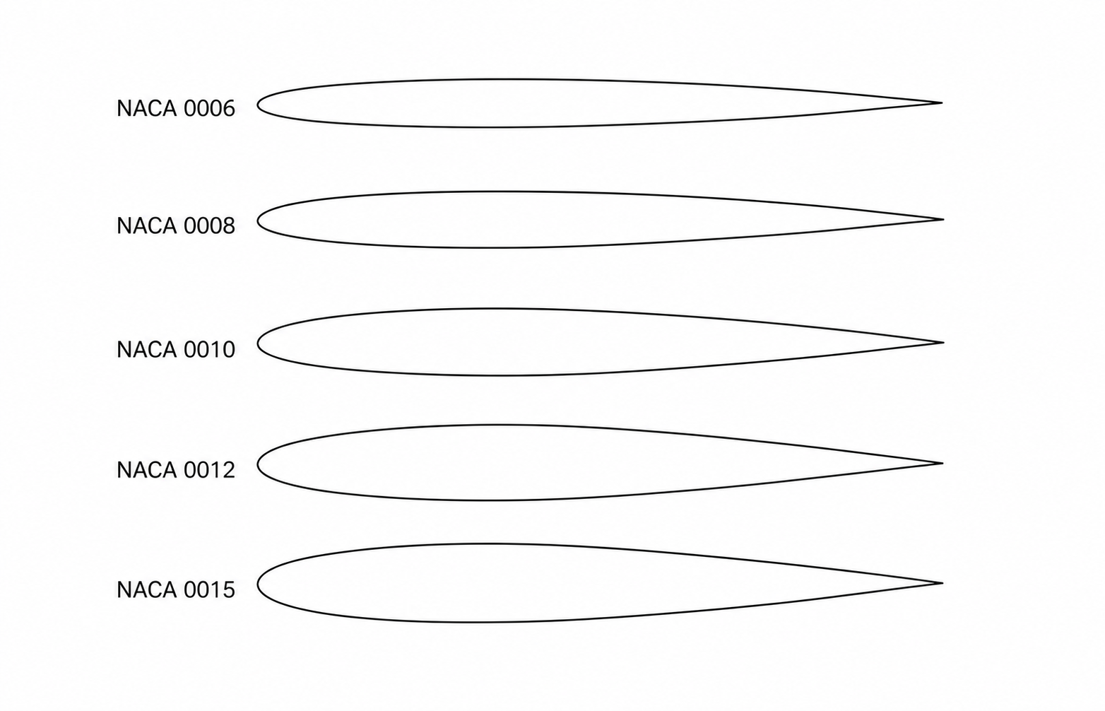
This is one reason I like the system, if somebody tells me a rudder uses a NACA 0015 section, I already know something useful about the geometry before seeing the drawing... by the way, you can play with the four-digit system below and watch the profile change as you move the numbers.
Why symmetric profiles make sense on a yacht
The NACA 00XX family started making sense to me first through the rudder: it has to generate force in either direction depending on whether it turns to port or starboard, so starting from a section with the same geometry on both sides is pretty logical.
Then the same idea begins appearing elsewhere; a sailing-yacht keel has to generate side force on one tack and then the opposite force on the other, so a symmetric section makes sense there as well. A published CFD study of an International America’s Cup Class yacht keel, for example, used NACA 0012 for the keel fin and winglets.
Stabilizer fins take the idea in another direction because the lift itself is being controlled to create a moment against roll; NACA 0015 sections have also appeared in active-fin research, where the direction of that force needs to alternate.
But that definitely does not mean every rudder, keel or stabilizer should suddenly become NACA 0012 or 0015. Marine-specific rudder profiles such as wedge-tail or fishtail sections, along with completely custom profiles, all exist for a reason. One study comparing several marine rudder families found that the NACA profiles tested had the highest lift-to-drag efficiency, while wedge-tail profiles produced stronger maneuvering forces.
Lift and drag
The basic reason any of this matters is that the appendage is there to generate force.
For a foil moving through water, lift can be written as:
and drag as:
where is the fluid density, is the flow speed, is the reference area, and and are the lift and drag coefficients.
The section shape affects those coefficients, but angle of attack quickly becomes part of the story as well: a symmetric NACA 0012 at zero angle should not produce meaningful lift in ideal symmetric flow, but rotate it slightly and the pressure distribution changes. Lift increases until separation becomes strong enough that the section approaches stall, while drag keeps growing with it.
On a rudder that lift becomes steering force, while the same basic mechanism lets a keel resist leeway and gives a stabilizer something it can use to fight roll; the geometry may be doing similar work underneath, but the reason we want that force changes with the appendage.
The in those equations matters a lot: the force grows very quickly with speed, and water is already much denser than air, so a relatively small appendage can end up carrying serious loads. Hydrodynamics and structure are definitely not separate conversations for very long.
Thickness
The last two digits are easy to read as only a hydrodynamic number, but going from NACA 0012 to NACA 0015 also gives the physical structure more room to exist.
A thicker rudder section creates more depth for the stock and internal structure, which can make the structural problem much easier; the outside shape has changed at the same time though, so the pressure distribution and drag move with it, along with things like the leading-edge radius and stall behavior.
This is where the profile stops being only a fluid problem for me: a very thin section may look attractive when you are only looking at drag, then you try putting an actual rudder stock through it and suddenly the structure starts arguing back 😅
The same problem gets more serious as the loads increase, with keels and hydrofoils sometimes pushing the profile in one direction hydrodynamically while the structure, manufacturing method or available internal space pushes it somewhere else.
Why NACA 0012 appears so often in CFD
This is another reason NACA 0012 keeps appearing everywhere: it is not necessarily because everybody thinks it is the perfect foil, but because we know so much about it.
The original NACA work contains lift, drag, pressure and surface-condition data for large families of sections, while later studies have repeatedly used NACA 0012 as a validation case. So before trusting a CFD simulation of some custom rudder that I created myself, I can first ask the solver to reproduce something that has already been measured properly.
That is extremely useful while I am developing my CFD work because a beautiful pressure plot proves almost nothing by itself; if the same setup can model a NACA 0012 at a known Reynolds number and angle of attack, then get reasonably close to published lift and drag data, I have a much better reason to trust what happens when I move to the custom geometry.
The Reynolds number becomes important here:
where is the chord length and is the dynamic viscosity.
Two geometrically identical NACA 0012 sections do not automatically behave the same way just because the profile name matches: change the speed or chord and the Reynolds number moves with them, while surface condition and turbulence can shift the behavior again.
So “NACA 0012” tells me the geometry; it definitely does not tell me the whole performance story.
From profile to appendage
Once the section becomes an actual rudder, span and planform start changing the flow around it; the tip and root now matter, and on a powered yacht the rudder may also be working inside a propeller slipstream rather than clean uniform flow.
A keel has its own version of the same problem because the section becomes part of a complete fin, sometimes with a bulb underneath it and the hull very close above. Hydrofoils take it further again because the free surface becomes difficult to ignore and both ventilation and cavitation can become serious limits as speed and loading increase.
Generating the geometry
Another useful thing about the four-digit NACA profiles is that I do not actually need a drawing to create one.
For a symmetric four-digit section, the half-thickness distribution is commonly written as:
where is the maximum thickness as a fraction of the chord, is the chord length and is the position along the chord.
For NACA 0012:
t = 0.12
and for NACA 0015:
t = 0.15
That is enough to generate the section directly in Python, Grasshopper, Rhino or another parametric tool; change the chord and the complete profile scales with it, which means the same definition can move quite easily from a small experiment into CAD or CFD.
There is also one tiny detail I really like here: the original four-digit equation using -0.1015 leaves a very small finite thickness at the trailing edge, while many geometry generators change that coefficient slightly to close it completely.
Sounds insignificant... until two tools give you slightly different geometry and you start wondering why 🤣